Difference between revisions of "Layout for DatLab graphs"
From Bioblast
m |
m |
||
| Line 21: | Line 21: | ||
[[File:Layout-menu.png|right|200px]] | [[File:Layout-menu.png|right|200px]] | ||
:::: Open this window (Section above) to view and edit information | :::: Open this window (Section above) to view and edit information and load or save a graph layout. | ||
::[[File:Info save.png|600px|Info load and save]] | ::[[File:Info save.png|600px|Info load and save]] | ||
::::: Types - Four types of layout can be selected depending on the O2k-configuration: | ::::: Types - Four types of layout can be selected depending on the O2k-configuration: | ||
:::::* O2: Oxygen channel | :::::* O2: Oxygen channel only. | ||
:::::* O2 & Amp: Oxygen and amperometric channel. | :::::* O2 & Amp: Oxygen and amperometric channel. | ||
:::::* O2 & pX: Oxygen and potentiometric channel. | :::::* O2 & pX: Oxygen and potentiometric channel. | ||
| Line 35: | Line 35: | ||
::: '''General information''' | ::: '''General information''' | ||
:::: Layouts 01 to 07 are considered for | :::: Layouts 01 to 07 are considered for O2 applications. | ||
:::: Layouts Amp* or pX* are selected for O2k-MultiSensor applications. | :::: Layouts Amp* or pX* are selected for O2k-MultiSensor applications. | ||
| Line 56: | Line 56: | ||
=== 01 Calibration show Temp === | === 01 Calibration show Temp === | ||
:::: ''' Calibration show temp''' shows | :::: ''' Calibration show temp''' shows O<sub>2</sub> concentration and the negative slope in Graph 1 and 2, and temperature and Peltier power in Graph 3: This is the default layout used after switching on the O2k for performing oxygen calibration. | ||
::::: Graph 1 & 2: | ::::: Graph 1 & 2: O<sub>2</sub> concentration (blue lines, left Y-axis) and O<sub>2</sub> slope negative (uncorrected; red lines, right Y-axis) are displayed in the top graph for the left chamber (A), and below for the right chamber (B). | ||
::::: Graph 3: The third graph (bottom) shows the block temperature on the left Y axis (red) and the Peltier power on the right Y axis (green). Only when both temperature and Peltier power are constant, the chambers have reached thermal equilibrium. | ::::: Graph 3: The third graph (bottom) shows the block temperature on the left Y axis (red) and the Peltier power on the right Y axis (green). Only when both temperature and Peltier power are constant, the chambers have reached thermal equilibrium. | ||
::::# During this phase a stirrer test can be performed [F9]. | ::::# During this phase a stirrer test can be performed [F9]. | ||
| Line 65: | Line 65: | ||
=== 02 Calibration - Background === | === 02 Calibration - Background === | ||
:::: Is used for recording | :::: Is used for recording O<sub>2</sub> sensor calibration and instrumental O<sub>2</sub> background test. 'O<sub>2</sub> slope neg.' is the negative slope of oxygen concentration, multiplied by 1000 to convert to units [pmol/mL], over time [s]. No correction is applied for instrumental O<sub>2</sub> background flux, J°<sub>02</sub>. 'O<sub>2</sub> slope neg.' is plotted on the right Y-axis with a scaling to display ±10 pmol∙s<sup>-1</sup>∙mL<sup>-1</sup> and zero in the middle of the Y2 axis. Zero slope in the 'open' chamber at air calibration indicates the stability of the oxygen signal. After closing the chamber, the slope deviates from zero as a function of the oxygen consumption of the polarographic oxygen sensor and of oxygen diffusion into or out of the chamber, which is the first point in the instrumental O<sub>2</sub> background test. | ||
::::» Further information: [[MiPNet14.06 Instrumental O2 background]] | ::::» Further information: [[MiPNet14.06 Instrumental O2 background]] | ||
=== 03 Background high O2=== | === 03 Background high O2=== | ||
:::: Is used for recording an instrumental | :::: Is used for recording an instrumental O<sub>2</sub> background test at high oxygen from 150 to 450 µM. | ||
=== 04a Flux per volume === | === 04a Flux per volume === | ||
:::: It displays background-corrected oxygen flux per volume, which is most relevant to evaluate experimental details, i.e. flux per volume is optimally in the range of 20 to 200-500 pmol∙s- | :::: It displays background-corrected oxygen flux per volume, which is most relevant to evaluate experimental details, i.e. flux per volume is optimally in the range of 20 to 200-500 pmol∙s<sup>-1</sup>∙mL<sup>-1</sup>. This plot is also chosen when measurements on sample density are available only at a later stage. Total O<sub>2</sub> flux is corrected for instrumental O<sub>2</sub> background, J°<sub>O2,V,</sub> to obtain sample oxygen flux per chamber volume, J<sub>O2,V</sub>(sample): | ||
J<sub>O2,V</sub>(sample) = J<sub>O2,V</sub>(total) - J°<sub>O2,V</sub> | J<sub>O2,V</sub>(sample) = J<sub>O2,V</sub>(total) - J°<sub>O2,V</sub> | ||
=== 04b Flux per volume overlay === | === 04b Flux per volume overlay === | ||
:::: It is similar to the layout ''04a Flux per volume''. Graph 1 shows the background-corrected oxygen flux per volume [pmol∙s- | :::: It is similar to the layout ''04a Flux per volume''. Graph 1 shows the background-corrected oxygen flux per volume [pmol∙s<sup>-1</sup>∙mL<sup>-1</sup>] superimposed from both chambers. Graph 2 shows oxygen concentration [µM]. | ||
=== 05a Specific flux === | === 05a Specific flux === | ||
:::: Is used for plotting background-corrected oxygen flux per unit sample. The unit as a marker for the amount of sample is defined in the F3 window. Example: Select ''Unit mg'' for the amount (mass) of sample added to the chamber. The mass-concentration is automatically calculated (division by chamber volume, typically 2 | :::: Is used for plotting background-corrected oxygen flux per unit sample. The unit as a marker for the amount of sample is defined in the F3 window. Example: Select ''Unit mg'' for the amount (mass) of sample added to the chamber. The mass-concentration is automatically calculated (division by chamber volume, typically 2 mL). Then mass-specific flux [pmol∙s<sup>-1</sup>∙mg<sup>-1</sup>] is displayed as volume-specific flux [pmol∙s<sup>-1</sup>∙mL<sup>-1</sup>] divided by mass-concentration [mg/mL]: | ||
J<sub>O2,mass</sub> = J<sub>O2,V</sub> / mass-concentration | J<sub>O2,mass</sub> = J<sub>O2,V</sub> / mass-concentration | ||
| Line 90: | Line 90: | ||
=== 06b Specific flux high 02 overlay === | === 06b Specific flux high 02 overlay === | ||
:::: As ‘06a Specific flux high O2’, but oxygen flux ( | :::: As ‘06a Specific flux high O2’, but oxygen flux (Graph 1) and oxygen concentration (Graph 2) superimposed from both chambers. | ||
=== 07a Flux control ratios === | === 07a Flux control ratios === | ||
:::: It shows the flux control ratio (FCR) and the oxygen concentration for the left chamber in | :::: It shows the flux control ratio (''FCR'') and the oxygen concentration for the left chamber in Graph 1 and for the right chamber in Graph 2. First, the reference and baseline metabolic states are marked and the marks are named (Marks \ Names). Then the marks are selected in the menu [[Flux/Slope]] \ O2 slope. | ||
=== 07b Flux control ratios overlay === | === 07b Flux control ratios overlay === | ||
:::: As ‘07a Flux control ratios’, but FCR (graph 1) and oxygen concentration (graph 2) superimposed from both chambers. | :::: As ‘07a Flux control ratios’, but ''FCR'' (graph 1) and oxygen concentration (graph 2) superimposed from both chambers. | ||
Revision as of 14:33, 7 December 2020
Description
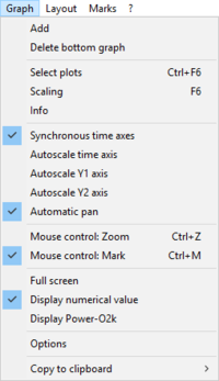
A Layout in DatLab from the Layout menu or the Graph menu is a predefined selection for standardized display of graphs, plots to be displayed at specific scalings. Any defined graph layout can be selected from the Layout menu for defining initial settings for the plots [Ctrl+F6] and scaling [F6]. A layout can be modified and saved under a specific name.
MitoPedia O2k and high-resolution respirometry:
DatLab
Graph / Info
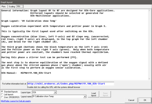
- View and edit information, and load or save a graph layout. (See below
- A quick selection of the tabs Plots Ctrl+F6 and Scaling (F6) is possible.
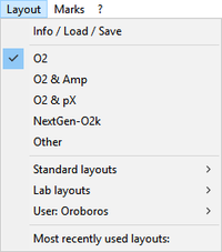
Layout: Info/ Load/ Save
Standard layouts - O2k-FluoRespirometer
Version: DatLab 7
- In typical standard DatLab graph layouts plots are shown for the left chamber in Graph 1 (top), and for the right chamber in Graph 2 (below). During data acquisition, a 30 min time range is frequently used and can be adjusted any time during the experiment [F6].
- General information
- Layouts 01 to 07 are considered for O2 applications.
- Layouts Amp* or pX* are selected for O2k-MultiSensor applications.
- General information
- Summary
- 01 Calibration show Temp
- 02 Calibration - Background
- 03 Background high O2
- ----
- 04a Flux per volume
- 04b Flux per volume overlay
- ----
- 05a Specific flux
- 05b Specific flux overlay
- 06a Specific flux high O2
- 06b Specific flux high O2 overlay
- ----
- 07a Flux Control Ratios
- 07b Flux Control Ratios overlay
- Summary
01 Calibration show Temp
- Calibration show temp shows O2 concentration and the negative slope in Graph 1 and 2, and temperature and Peltier power in Graph 3: This is the default layout used after switching on the O2k for performing oxygen calibration.
- Graph 1 & 2: O2 concentration (blue lines, left Y-axis) and O2 slope negative (uncorrected; red lines, right Y-axis) are displayed in the top graph for the left chamber (A), and below for the right chamber (B).
- Graph 3: The third graph (bottom) shows the block temperature on the left Y axis (red) and the Peltier power on the right Y axis (green). Only when both temperature and Peltier power are constant, the chambers have reached thermal equilibrium.
- During this phase a stirrer test can be performed [F9].
- The next step is to observe equilibration of the oxygen signal with a defined gas phase above the stirred aqueous phase ('open') chamber; usually with air as the first step to perform an oxygen sensor calibration.
- Calibration show temp shows O2 concentration and the negative slope in Graph 1 and 2, and temperature and Peltier power in Graph 3: This is the default layout used after switching on the O2k for performing oxygen calibration.
- » Further information: O2 calibration - DatLab
02 Calibration - Background
- Is used for recording O2 sensor calibration and instrumental O2 background test. 'O2 slope neg.' is the negative slope of oxygen concentration, multiplied by 1000 to convert to units [pmol/mL], over time [s]. No correction is applied for instrumental O2 background flux, J°02. 'O2 slope neg.' is plotted on the right Y-axis with a scaling to display ±10 pmol∙s-1∙mL-1 and zero in the middle of the Y2 axis. Zero slope in the 'open' chamber at air calibration indicates the stability of the oxygen signal. After closing the chamber, the slope deviates from zero as a function of the oxygen consumption of the polarographic oxygen sensor and of oxygen diffusion into or out of the chamber, which is the first point in the instrumental O2 background test.
- » Further information: MiPNet14.06 Instrumental O2 background
03 Background high O2
- Is used for recording an instrumental O2 background test at high oxygen from 150 to 450 µM.
04a Flux per volume
- It displays background-corrected oxygen flux per volume, which is most relevant to evaluate experimental details, i.e. flux per volume is optimally in the range of 20 to 200-500 pmol∙s-1∙mL-1. This plot is also chosen when measurements on sample density are available only at a later stage. Total O2 flux is corrected for instrumental O2 background, J°O2,V, to obtain sample oxygen flux per chamber volume, JO2,V(sample):
JO2,V(sample) = JO2,V(total) - J°O2,V
04b Flux per volume overlay
- It is similar to the layout 04a Flux per volume. Graph 1 shows the background-corrected oxygen flux per volume [pmol∙s-1∙mL-1] superimposed from both chambers. Graph 2 shows oxygen concentration [µM].
05a Specific flux
- Is used for plotting background-corrected oxygen flux per unit sample. The unit as a marker for the amount of sample is defined in the F3 window. Example: Select Unit mg for the amount (mass) of sample added to the chamber. The mass-concentration is automatically calculated (division by chamber volume, typically 2 mL). Then mass-specific flux [pmol∙s-1∙mg-1] is displayed as volume-specific flux [pmol∙s-1∙mL-1] divided by mass-concentration [mg/mL]:
JO2,mass = JO2,V / mass-concentration
05b Specific flux overlay
- It is similar to ‘05a Specific flux’. Graph 1 shows the background-corrected oxygen flux per unit sample superimposed from both chambers. Graph 2 shows oxygen concentration [µM].
06a Specific flux high O2
- This is the same as ‘05a Specific flux’ with the scaling adapted to the high oxygen concentration used for permeabilized muscle fibers (150 to 450 µM; range 300 µM).
06b Specific flux high 02 overlay
- As ‘06a Specific flux high O2’, but oxygen flux (Graph 1) and oxygen concentration (Graph 2) superimposed from both chambers.
07a Flux control ratios
- It shows the flux control ratio (FCR) and the oxygen concentration for the left chamber in Graph 1 and for the right chamber in Graph 2. First, the reference and baseline metabolic states are marked and the marks are named (Marks \ Names). Then the marks are selected in the menu Flux/Slope \ O2 slope.
07b Flux control ratios overlay
- As ‘07a Flux control ratios’, but FCR (graph 1) and oxygen concentration (graph 2) superimposed from both chambers.
Lab layouts
- A Standard layout or any other layout can be modified and saved under Lab layouts, which is recommended for a team using project-specific layouts.
User: Name
- A Standard layout or any other layout can be modified and saved under a specific user name, which is recommended to distinguish individual layouts from standard layouts used by a team.
Reference Layouts
Reference Layouts: O2 & Amp
Version: DatLab 7
- 01 Amp Amperometric_Raw signal
- 02 Amp Amperometric_Calibrated
Reference Layouts: O2 & pX
Version: DatLab 7
- 01 Potentiometric
- ----
- 02a TPP_calibration
- 02b TPP_with_O2flux
- 02c TPP_calibrated_with_O2flux
Reference Layouts: Other
Version: DatLab 7
- O2 raw signal


