 |
Oxygen signal |
MitoPedia O2k and high-resolution respirometry:
O2k-Open Support
Description
The oxygen signal of the Oroboros O2k is transmitted from the electrochemical polarographic oxygen sensor (OroboPOS) for each of the two O2k-chambers to DatLab. The primary signal is a current [µA] which is converted into a voltage [V] (raw signal), and calibrated in SI units for amount of substance concentration [µmol·L-1 or µM]. For technical reasons, the raw signal is given in [V] (DatLab 7 and previous) or [µA] (DatLab 8). The value of the raw signal is the same, independent of the displayed unit ([V] or [µA]). In the following sections, only [µA] is used for information on the raw signal, but the same values in [V] apply for the raw signal when using DL7 or previous versions.
Reference: MiPNet06.03 POS-calibration-SOP, MiPNet28.10 SmartPOS-service
MitoPedia O2k and high-resolution respirometry:
O2k-Open Support
Oxygen signal without calibration
- Without oxygen calibration in DatLab, the default oxygen signal is shown in units of O2 concentration [µM], but the numbers shown as a default are different from the real O2 concentration. The non-calibrated default values are calculated on the basis of the following default settings, which apply initially when no calibration was performed previously in DatLab, or when the Reset to system default button is clicked in the O2 calibration window:
- POS signal recorded; R1 = 2 µA (at air saturation)
- POS signal recorded; R0 = 0 µA (at zero oxygen concentration)
- Temperature = 37.00 °C
- Barometric pressure, pb = 100 kPa
- O2 solubility factor of medium, FM = 1.00
- These default settings result in a calculated O2 concentration at air saturation of 207.32 µM.
- Without oxygen calibration in DatLab, the default oxygen signal is shown in units of O2 concentration [µM], but the numbers shown as a default are different from the real O2 concentration. The non-calibrated default values are calculated on the basis of the following default settings, which apply initially when no calibration was performed previously in DatLab, or when the Reset to system default button is clicked in the O2 calibration window:
Oxygen signal after calibration
- After applying the oxygen calibration in DatLab the default settings are replaced by the actually measured and recorded signals of oxygen, temperature, and barometric pressure. The oxygen solubility factor has to be entered digitally. Subsequently, the new default settings correspond always to the latest calibration performed while DatLab is connected to the O2k which must be switched on. When applying the oxygen calibration, the oxygen signal of the entire plot in the DatLab file is calibrated.
Raw signal
- The raw signal of the polarographic oxygen sensor (POS) depends on the Gain setting. The default is Gain 1 from O2k-G onwards and NextGen-O2k (Gain 2 in previous O2ks). The maximum signal is 10 µA. Above 9.99 µA, the amplifier is in the saturation range, the apparent signal will remain constant at this value, and the slope will appear to be zero. The raw signal can be modified by choosing an appropriate Gain setting.
- The raw signal observed during calibration at air saturation depends on experimental temperature, barometric pressure (lower values are obtained above sea level), and the sensitivity of the individual POS. The raw signal is converted to oxygen concentration [µM or nmol/mL] or partial oxygen pressure [kPa] by calibration of the POS. Each gain requires a separate calibration of the oxygen signal. Therefore, after changing the gain you should not only perform a calibration at air saturation (as always before an experiment), but also a new zero oxygen calibration.
- Raw signal at air saturation, R1
- The raw signal recorded at air saturation and with an open chamber is an important instrumental quality parameter (QC1: Oxygen sensor test). R1 should be between 1 and 3 µA at 25 to 37 °C (up to 1000 m above sea level; barometric pressure 101 to 90 kPa)
- R1 is higher than recommended:
- If the recorded value is too high, first check the zero current (R0). A high zero current will also give a correspondingly higher signal at air saturation (R1); e.g., if the zero current corresponds to 1 µA at Gain 1, the raw signal at air saturation will typically be 3 µA instead of 2 µA.
- If the zero current is too high a leak current test or switch components approach help to locate the problem.
- If the zero current is as recommended, consider the following potential reasons for changes in R1:
- The stirrer speed (rpm) may have been changed, or the stirrer may have been left in the off mode. - Re-set the stirrer speed and re-calibrate.
- The gain setting may have been changed. - Compare calibration values at identical gain settings.
- The block temperature may have been changed. - Compare calibration values at identical temperatures.
- The barometric pressure has changed (e.g., experiments carried out at high altitude).
- The membrane may have been overstretched, or a thinner membrane is used. - Apply a new membrane, following POS-Service instructions: MiPNet19.18B POS-service, MiPNet28.10 SmartPOS-service.
- R1 is zero or lower than recommended:
- If the problem occurred after application of a new membrane:
- The membrane thickness may have changed, possibly by inadvertently using two superimposed membranes.
- The membrane may have wrinkles in the area of the cathode. - For both cases (1 and 2), apply a new membrane, following POS-Service instructions: MiPNet19.18B POS-service, MiPNet28.10 SmartPOS-service.
- The POS-Seal Tip may have not been applied properly in the center, now partially blocking the cathode. - Correct the position of the POS-Seal Tip.
- If the problem occurred after re-assembly of the O2k-chamber the chamber may have been improperly positioned, with the blue POS holder (on the left or right side of the copper block) screwed too far into the chamber housing. This would allow only partial contact between the stirred medium and the cathode. - Follow the O2k manual and video support (A2 Insert O2k Chamber) instructions to insert the chamber properly.
- If the problem occurred after the O2k has not been used in a while or due to improper POS storage, the electrolyte in the POS may have partially dried out. - Apply a new membrane, following POS-Service instructions: MiPNet19.18B POS-service, MiPNet28.10 SmartPOS-service.
- If the problem occurred after temporarily removing the POS from the POS-Holder or disconnecting the OroboPOS from the OroboPOS-Connector it is likely the POS was not re-inserted correctly or the OroboPOS was not properly screwed onto the OroboPOS-Holder.
- To evaluate if this is causing the problem, perform the following test:
- Start a measurement with deionized or double distilled water and record for 5 minutes.
- Empty the chamber, set an event (F4) called “Empty chamber” and record for 2 minutes
- Remove the POS from the POS-Holder but leave the OroboPOS screwed to the OroboPOS-Connector. Keep the SmartPOS or OroboPOS-Connector plugged to the main unit. Set an event (F4) called “POS removed” and record for 3 to 5 minutes.
- If the signal does not increase after removing the POS, check if the POS is completely screwed to the POS-Connector and, if not, screw it more tightly. Set an event (F4) called “POS screwed”. If the signal does still not increase contact our technical support.
- If the signal increases, there could be a problem with an incorrect positioning of the chamber.
- Insert the POS into the POS-Holder, making sure the OroboPOS is properly screwed to the OroboPOS-Connector. Set an event (F4) called “POS inserted”. Record for 3 to 5 minutes.
- Check if after reinserting the POS, the signal goes back to recommended values. If the signal continues lower than recommended, reassemble the glass chamber.
- To evaluate if this is causing the problem, perform the following test:
Keywords: Oxygen signal
- Bioblast links: Oxygen signal - >>>>>>> - Click on [Expand] or [Collapse] - >>>>>>>
- Specific
- O2k-Procedures
- MiPNet O2k-Procedures
- Other keyword lists
Problems - solutions
Instability of the oxygen signal
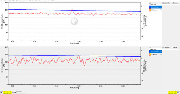
- The stability of the oxygen signal of the O2k is evaluated by the (negative) uncorrected slope over time. After smoothing, the slope of a stable sensor should be less than ± 1 pmol·s-1·mL-1 in a 2-mL O2k chamber.
- Instability of the oxygen signal
- There is drift of the oxygen signal over short or long periods of time.
- The signal at air saturation is abnormally high for a given gain setting.
- The zero current is high (>2.5%) and may show drift.
- Follow the SOP instructions: MiPNet06.03 POS-calibration-SOP.
Oxygen signal does not respond
- Check the raw signal
- If the raw signal is at the measurement limit (10 µA) or 0, check the gain setting for the affected oxygen channel (Standard setting: Gain 1). If the gain is set to 1, please follow the instructions above for a high or low R1.
- If the raw signal is in the recommended range contact our technical support.
Troubleshooting
Anonymous user
Question:
Q1: The Oxygen Concentration couldn't go down while I tried zero oxygen calibration. No matter how much solution I added, the oxygen concentration still remain the same. I reassembled, but it still keeps the same. The data is attached.
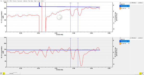
Q2: The chamber B's oxygen slope is not stable. This is a new problem I have never seen. Please see the attachment.(2019-04-26)
Q3. The maximum Oxygen concentration of another Oroboros O2k is only about 140 μM. I don't how to increase the starting point of oxygen concentration.
Answer:
A1: I suspect that the dithionite solution was not correctly prepared or not fresh. Dithionite loses activity quite fast, so you need to make it freshly. Please check this site: http://bioblast.at/index.php/Dithionite
A2: While there is a difference between chambers A and B, the stability of the signal is still within the acceptable range of noise given by the specifications of the instrument, see: Oxygen_sensor_test.
A3: You may simply need to calibrate, please see here: http://wiki.oroboros.at/index.php/O2_calibration_-_DatLab
MitoPedia methods:
Respirometry
MitoPedia O2k and high-resolution respirometry:
DatLab,
O2k-Open Support


